It eauals the largest frequency a full-power ie V o V sine wave can obtain without being distorted by slew rate limiting. Given the values of a b a and v the value of the half-power frequency can be calculated.
 Overestimation Of Damping When Using The Half Power Bandwidth Method Download Scientific Diagram
That is at a level of approximately -3 dB.

Half power bandwidth formula. Some specifications may mandate 100 of the rated power. The power bandwidth of an amplifier is sometimes taken as the frequency range or rarely the upper frequency limit for which the rated power output of an amplifier can be maintained without excessive distortion to at least half of the full rated power. Antenna beam width is also known as the half-power.
The conversion formula is f f Q n 2 where f n is the natural frequency. O0 oo12 112 As we see from the plot on Figure 2 the bandwidth increases with increasing R. It provides Resonant frequency Surface resistance unloaded Q factor and Half Power Bandwidth as outputs.
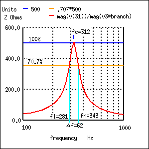
Sometimes referring to the full-power bandwidth. BW Df f h -f l 343-281 62 f l f c - Df2 312-31 281 f h f c Df2 31231 343. Of EECS Full-Power bandwidth The value.
What do you mean by 3 dB cutoff frequency. 34 always gives a solution to the half-power frequency. Value at omega 0.
Q fcBW 312 Hz 62 Hz 5. Beam with70lambda_D Where lambda is wavelength l 03frequency. This full power region is the region from 0 HzDC to the frequency at which the power output is half its DC power.
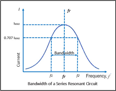
We can also name these two frequencies as Half Power frequencies since voltage gain drops to 707 of the maximum value. Beamwidth 70l D. Visit Circular Cavity Resonator.
05 I2 R 0707 x I2 R. The upper and lower band edges read from the curve are 281 Hz for fl and 343 Hz for fh. Where l Wavelength D Diameter l 03 frequency.
Thus if the input signal to oVSR. The unit of HPBW is radians or degrees. For calculating half power frequency they set it equal to cfrac12 which I think is the max.
The half-power bandwidth method for estimation of the damping ratio. At the cut-off frequency half-power frequency the less interesting power P is always fallen to 12 05 50 and the power level is damped by 10 log 12 30103 dB that is the same dB value. O M SR V is called the full-power bandwidth of the op-amp given a DC supply V.
Consequently the half-power frequency equation depends on the value of the fractional-order element a v and the transfer function parameter value a b. The half-power point or half-power bandwidth is the point at which the output power has dropped to half of its peak value. Antenna 3dB Beam width is the angle between the half-power of an antenna pattern or beam over which the relative power is at or above 50 of the peak power.
In filters optical filters electronic amplifiers the half-power point is a commonly used definition for the cutoff frequency. In the characterization of antennas the half-power point relates to measurement position as an angle and describes directionality. The formula or equations used in RF calculator are also mentioned.
Why is it 3 dB not 1 dB. The bandwidth is 62 Hz and the half power points are 31 Hz of the center resonant frequency. This is often confusing.
An op-amp circuit is a. The frequency f2 lies along with a high-frequency range and f1 in the low-frequency range. These -3dB points give us a current value that is 707 of its maximum resonant value which is defined as.
This is the region where the amplifier has the highest gain. Qffiffiffiffiffiffiffiffiffiffiffiffi 2 9Xr djoth9 ¼ 12x 1u0002x can be easily found. For small values of x leads to the formula or ffi on ie oon ¼1.
Can anyone please explain why this difference in solving the problems. The -3 dB points are also referred to as the fihalf power pointsfl on the transfer magnitude curve. The full-power bandwidth of an op amp is the range of frequencies in which an op amp operates with full power.
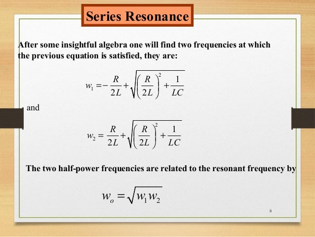
This video will clear your concepts regarding half power points and bandwidth in RLC series circuit. The bandwidth is the difference between the half power frequencies Bandwidth B o2o1 111 By multiplying Equation 19 with Equation 110 we can show that o0 is the geometric mean of o1 and o2. 07071 07071 is 05 and P V²R.
Based on the half-power bandwidth corrected analytical approximate formulas 11 for damping ratio were established by using displacement and acceleration FRFs respectively. The mathematical expression for half power beam width is Half. The figure shows half-power points on the major lobe and HPBW.
First Null Beam Width. This represents the power level of one half of the power at reference frequency in the mid-range frequency. This RF calculator calculates power units and frequency.
342011 Full Power Bandwidth lecture 67 Jim Stiles The Univ.
 Method To Calculate F 1 And F 2 Half Power Values For The Half Power Download Scientific Diagram
 4 Overestimation Of Damping When Using The Half Power Bandwidth Method Download Scientific Diagram
 Half Power Points Youtube
 Series Resonance In A Series Rlc Resonant Circuit
 Overestimation Of Damping When Using The Half Power Bandwidth Method Download Scientific Diagram
 Bandwidth Of Resonant Circuits Gbc Electronics Technician
 Half Power Frequency An Overview Sciencedirect Topics
 Q Factor And Bandwidth Of A Resonant Circuit Resonance Electronics Textbook
 Half Power Bandwidth Method Download Scientific Diagram
 Resonant Circuits
 Series Resonance In A Series Rlc Resonant Circuit
Calculating Half Power Frequency Frequency Response Physics Stack Exchange
 Calculating Half Power Frequency Frequency Response Physics Stack Exchange